FEATURES OF DRAFTER
Drafter automatically creates drawing of longitudinal cross-sections and schemas of pipe networks, pipelines and so on. It was developed to work especially with sewage networks, however it can be successfully used for other systems like: water supply, gas or drainage.
Drafter offers help from entering the data of nodes, automatically calculating some values, until a pipe network drawing is generated. The drawing can be modified in most CAD applications or printed directly from Drafter.
Drafter:
- automatically determines characteristic values (including by calculation, interpolation and autocomplete),
- allows to create drawings: longitudinal and vertical cross-sections, schemas,
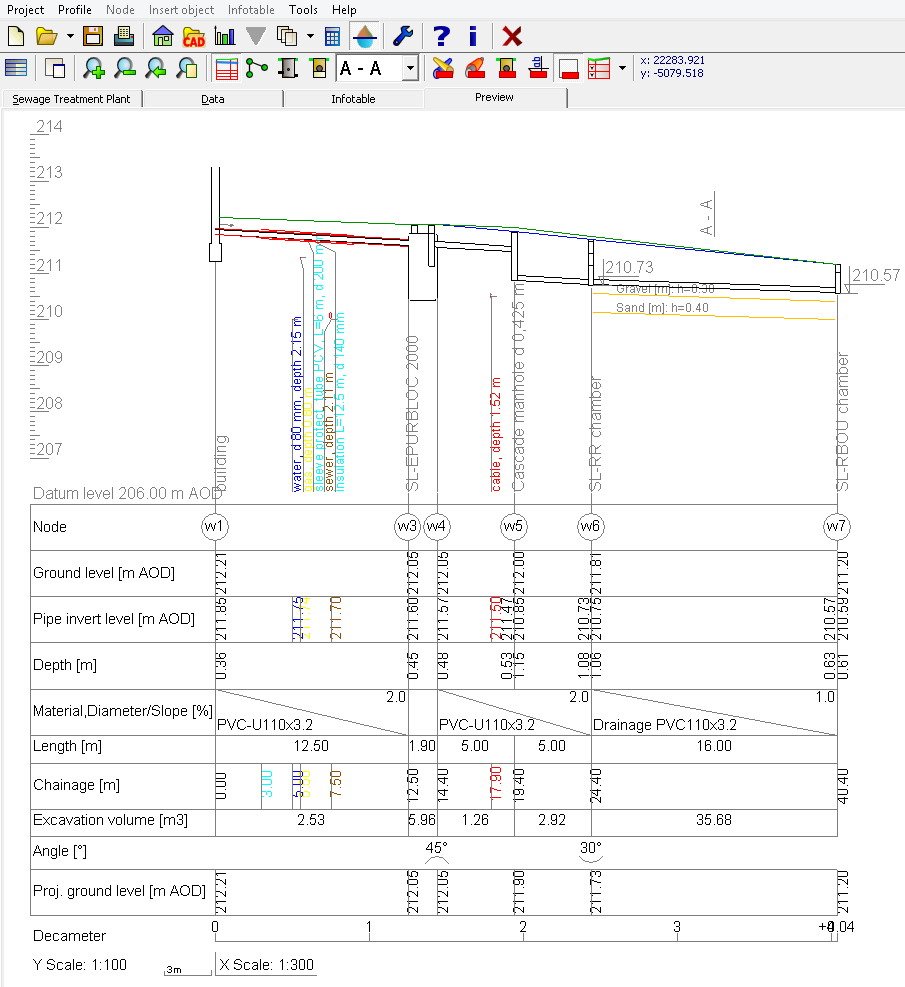
Longitudinal section sample 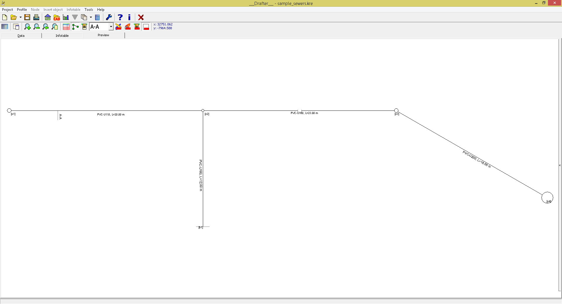
Scheme drawing sample 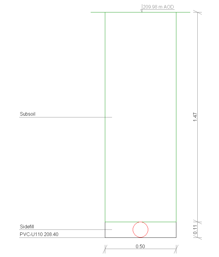
Cross-section drawing sample - generates drawings in the vector format DXF (possibility of further processing in CAD type applications),
- allows to import of nodes and crossings from DXF files (maps),
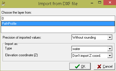
Importing coordinates from DXF files - allows direct printing generated drawings without any additional software,
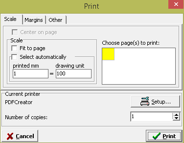
Printing settings window - includes objects, e.g.: septic tanks, manholes, dampers, pipes, with ability to create the own ones,
- generates pipe networks statistics (excavation volume and area, minimal and maximal: depth and drop, etc.),
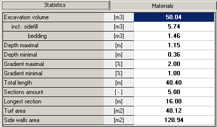
Statistics of the project - allows to export of data to applications allowing among other further analysis of flows: Epanet and EPA SWMM,
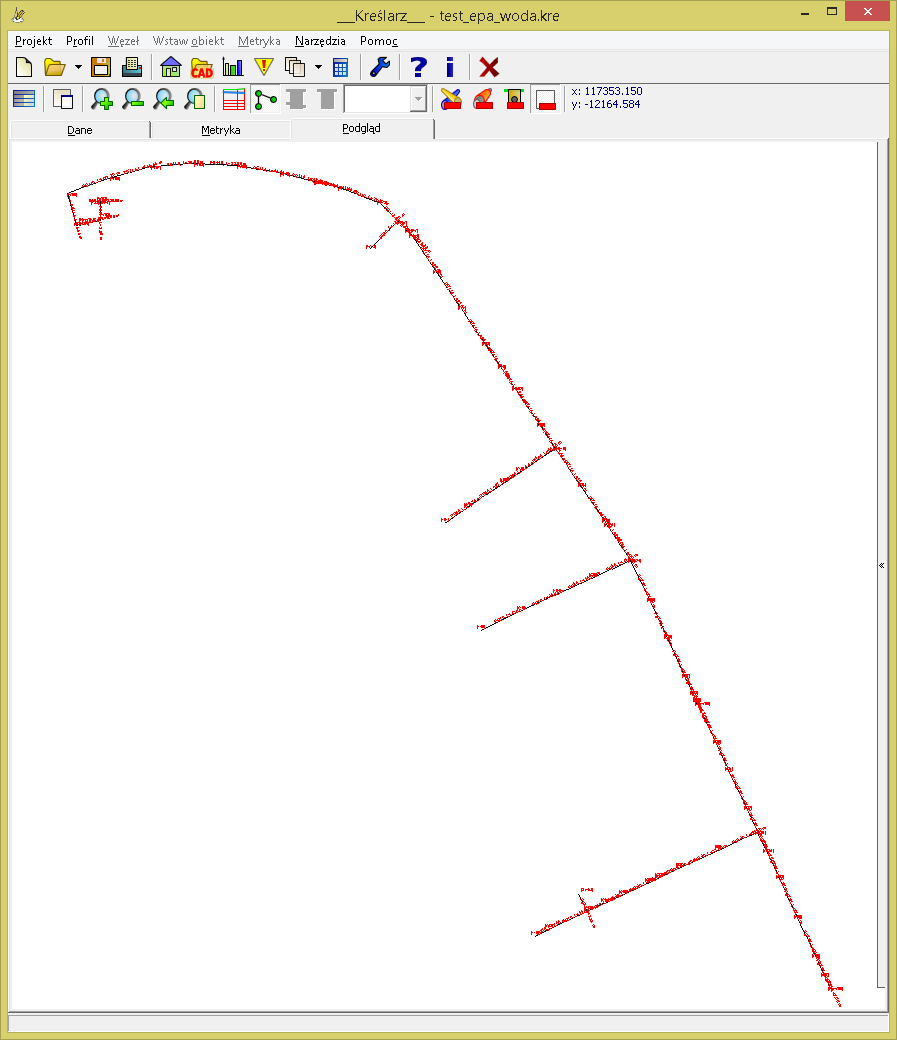
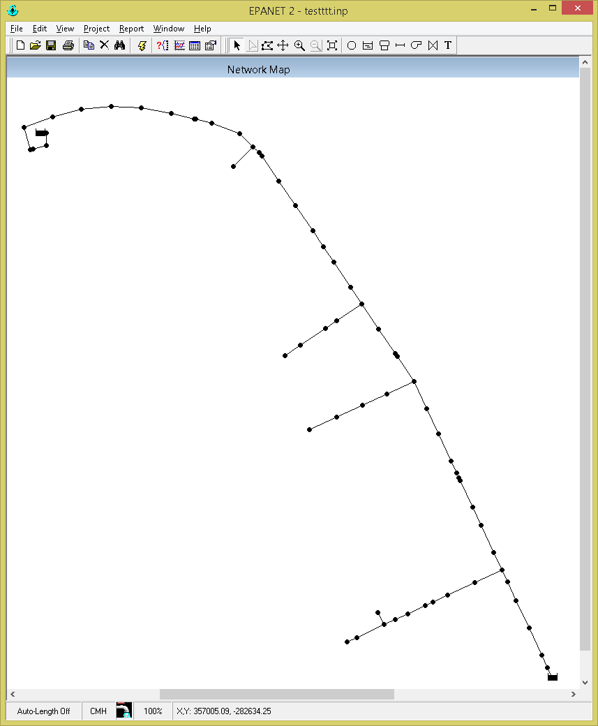
Schema of the water distribution network in the Drafter (left) and in Epanet, loaded from a file exported form the Drafter (right) - greatly speeds up the creation and modification of drawings,
- is flexible - has many configuration options.