DATA IMPORT FROM DIGITAL MAPS SAVED AS .DXF FILE
Importing data from digital maps with .dxf extension
In Drafter it is possible to import from a digital map coordinates of junctions of the pipeline that you are currently projecting. The file containing the map should be defined as .dxf and saved as text type document (it is sometimes called as ASCII with ANSI character encoding). In case of having your digital map saved as .dwg, you should export it as .dxf using your CAD app.
To import your file, choose in menu Profile > Import of coordinates from DXF file and next choose a proper file, from which junctions will be imported from.
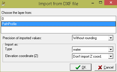
Next, in Import of coordinates from DXF file window, choose a layer from which junctions will be imported from. Junctions/points in .dxf file must be defined as lines or polylines and they cannot be located inside a BLOCK section. When the layout you imported to the Drafter will not belong together (will be consisted of separated fragments), then try to retry a importing procedure with limited decimal places of imported numbers.
You can also define type of imported pipeline in dropdown list Type. If imported junctions have their height coordinate "Z" defined in .dxf file, you can choose as which argument it will be imported (for example as ordinate of ground, ordinate of the pipe etc.). Not importing a "Z" coordinate is set as a default option. "Z" coordinate can be attributed in most of CAD programs. It can be done only to line type objects - it is not possible to polylines.
If Calculate length and angle from coordinates option is checked Tools > Settings > "Data" table > Table parameters, the Drafter will automatically calculate distances between junctions and angles between segments, based on the entered data. Other parameters are needed to be entered by the user (ordinate of ground, ordinate of the pipe etc.).
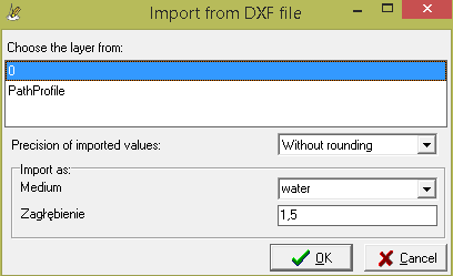
If imported .dxf file includes another network/pipeline which is not the one that you are working on, but colliding with it, you can optionally import that collisions to the Drafter. To do that choose from menu: Profile > Import collision from DXF file and select proper file and layer including a colliding network. You can also define a network type and depth of the imported collisions. You need to check in Settings window Crossing's depth is constant option by choosing menu: Tools > Settings > Others > Crossings Editor to make the entered depth of collision applied. Then you can enter some missing properties of collision in Crossings editor.