OBJECT PARAMETERS - DITCH
Modification of ditch-type objects
The "ditch" object allows to insert a cross-section through a ditch or slope (depending on the user settings) in the longitudinal profile drawing. The user can change the following parameters of the object:
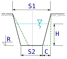
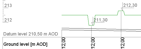
- Bottom ordinate - R [m AOD] - this value can be defined as lower or higher than the ground level at a given node. A smaller value results in a ditch (on the figure below, left), while a larger value results in an escarpment (on the figure below, right). Using the version with an escarpment and setting its width appropriately, it is possible to obtain e.g. a cross-section of a road under which the designed pipeline passes. By default, the value of the trench bottom ordinate is assumed 0.5 m lower than the value of the pipe bottom ordinate at the given node.
- Width - top - S1 [m] - width of the trench at ground level. The default value is 0.50 m.
- Bottom Width - S2 [m] - the width of the bottom of the ditch (or top of the slope). The default value is 0.35 m.
- Bottom horizontal correction - C [m] - horizontal bottom shift allows to obtain asymmetric slope inclination. The default value is 0.00 - which means that the slopes are inclined to the bottom at the same angle.
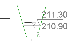
- Water table level - H [m] - if necessary, you can plot the water level on the ditch cross-section (example in the following figure), expressing it in meters as the vertical distance from the ditch bottom. By default, this level is not marked.