OBJECT PARAMETERS - BUILDING
Modification of building type objects
The "building" object allows to mark a passage through a wall on a longitudinal profile drawing. The user can define the following parameters of the object:
- Footing bottom depth [m] - this is the vertical distance between the ordinates of the existing terrain (or designed terrain, if the Count depth in relation to the projected ground level option is selected in the Configuration window) and the bottom of the footing. Default value is 0.6 m below the ordinate of the pipe bottom in a given node.
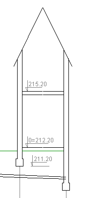
- Floor ordinate(s) [m AOD] - One or more (for multi-storey buildings) ordinates separated by semicolon ";" can be given. If the floor ordinate is not given, it will not be included in the drawing. The exception is when the floor length is given - then the top of the floor is equal to the ground level. To avoid plotting the ordinate on the drawing, precede the ordinate with "x". The ordinate which is to be marked as so called zero of the building should be preceded by zero.
- Ceiling length [m] - A negative length value places the floor drawing on the left side of the wall, while a positive value places it on the right. Default value is -1.5 m.
- Ceiling thickness [m] - Default value is 0.2 m.
- Wall extra height [m] - Additional height of the wall above the highest ceiling. Default value is 0.1 m.
- Roof - When checked, the roof outline is plotted on the drawing.
- Roof pitch angle [°] - Determine angle of roof slope inclination to horizontal. For the roof to be drawn, the Roof option must be checked. The default value is 45°.
- Depth of the bottom of footing count to "0" - Selecting this option causes calculation of footing bottom depth as a difference between "zero" of the building ordinate (it must be marked) and value given as Footing bottom depth.
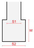 Wall thickness - S1 [m] - Definition of the wall thickness. Default value is 0.5 m.
- Footing width - S2 [m] - Defines the width of the footing. Default value is 0.8 m.
- Footing height - W [m] - Defines the height of the footing. Default value is 0.4 m.
- Angle between pipe and wall [°] - Specify the horizontal angle between the pipe entering the building and the wall. The default value is 90° when the pipe enters perpendicular the wall plane.
It is possible to draw the outline of the whole building (as in the first picture). To do that, a building object with the same parameters should be inserted into two adjacent nodes, except for the negative value of the floor length in the node on the right.
The above parameters can also be defined for other objects using the building outline, i.e.: gutter (additionally you can specify its diameter), water meter set (additionally you can specify the diameter of the casing pipe between the building wall and fittings - the pipe will not be drawn if you do not specify its diameter), gasbox on the wall.