PRINT PREVIEW
Print preview
To view the generated drawing, click on the Preview tab in main window of the Drafter. The Drafter can generate the following drawings:
- longitudinal cross-section,
- diagram, i.e. for example the network with the connections as seen as on a map,
- cross-section through manholes, without having to define it in the Cross-section Editor,
- cross-section defined in the Cross-section editor at any point in the pipeline (also through manholes and tanks).
The following describes functions of the buttons on the tab:
- zoom in, (also key + on numeric keyboard)
- zoom out, (also key - on numeric keyboard)
- original size,
- previous view.
User can hide/show some groups of elements of the drawing by pressing below mentioned buttons:
- crossings,
- sleeve protecting tubes,
- vertical cross-sections,
- parcel boundaries,
- pagination.
Marking of collisions and plot boundaries in the schematic drawing is in a simplified version, i.e. it does not take into account the angle projected on the horizontal plane between the projected pipeline and the collision or the plot boundary (in the schematic it is always a right angle: 90 degrees). Objects located in the hidden part of the "shortened" pipeline are not shown in the schematic drawing (when using the option: Trim sections longer than...).
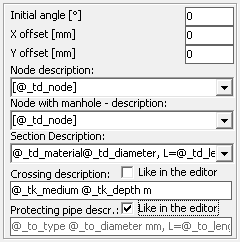
 Additionaly after Panel activation (by pressing F4 key) following options are available to adapt the scheme drawing:
- Determining the initial angle of the scheme.
- X Offset - Horizontal offset from the position imposed automatically by the program.
- Y Offset - Vertical offset from the position imposed automatically by the program.
- Node description - pattern of node descriptions.
- Description of a node with a manhole - template according to which descriptions of nodes where the Manhole object is located will be applied.
- Section description - pattern of section descriptions.
- Crossing description - a template according to which crossings descriptions will be applied to the profile and scheme drawings.
- Sleeve protecting pipe description - template according to which the sleeve protecting pipe descriptions will be applied on the profile and scheme drawings.
By unchecking the Like in the editor checkbox, a template for the description of the crossing and protecting pipes can be imposed (independently). With this option selected, the descriptions from the respective editors will be used.
In the node and section descriptions, the variables (located in the Data table section) should be used. On the other hand, in the crossing and protecting pipe descriptions, the variables placed in the crossings and protecting pipe sections respectively. Inserting \P in the body of the description of a node and in the description of a node with a manhole moves the fragment of text behind the \P to a new line.
By clicking Open preview in new window can move the preview to the new window. This allows you to "live" observe the impact of changes on the created drawing. This option can significantly improve the ease of working with computers designed for simultaneous display on two monitors. Not recommended for use in a separate preview window for older computers.
Hints:
- double clicking the left mouse button anywhere in the preview is the place to move to the center of the preview,
- circle with the mouse any viewing area, with the left button, causes its enlargement,
- moving the mouse while pressing the right button to move the generated drawing,
- mouse wheel rotation, depending on its direction, causing zooming in or out of the picture,
- drawing can be moved using the cursor keys,
- hold Ctrl key while pressing the cursor keys result in faster movement.
Current version:4.20
