ENTERING CROSS-SECTIONS INTO THE PROFILE
Entering cross-sections into the profile
| icon: | menu: Tools > Section Editor |
 | keyboard shortcut: Ctrl+T |
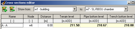
Cross-section editor is used to define cross-sections of designed network. The cross-sections should be entered after entering data in Data table in the main window of Drafter. The user can narrow down the number of presented cross-sections by selecting nodes between which they are located.
Cross-sections are marked on profile and scheme drawings. Cross-sections can also be generated as separate drawings.
Description of each column in the Editor:
- Name - the name of the cross section (e.g. A-A).
- Node - name of the node (from the Data table) to which the distance to the section will be given. When editing this value, the user must select a node from the list of already existing ones. The cross-section is assigned to the selected node, i.e., the user can freely change its position in the Data table without having to update the section position each time.
- Distance - the distance from the node in the Node column to current cross-section. The value can be negative if it refers to a node that exists after the section.
- Terrain level - the ordinate of the terrain in the selected section (read-only value).
- Pipe bottom level - the ordinate of the pipe bottom in the selected section (read-only value).
- Trench bottom level - the ordinate of the bottom of the trench in the selected section (read-only value).
- Geo - clicking in Geo column allows to add/edit geotechnical cross-section of soil layers in the cross-section area.
Current version:4.20
- Data table
- Data table - shortcuts
- Entering data
- Data exchange
- Network creating rules
- Searching data
- Profile parameters
- Crossings editor
- Protecting tubes editor
- Cross section editor
- Geological cross section
- Terrain description
- Boundaries description
- Additional ordinates
- Sewage treament plant
- Manholes
- Statistic
- Statistic - algorithms
- Materials' list