DRAWING PARAMETERS
Settings - Drawing
Menu: Tools > Settings > Drawing
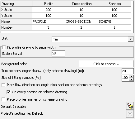 In the Settings window on the Drawing tab is possible to set for drawings (longitudinal section, schema, cross-section):
- scale, independent for X and Y axis,
- name,
- number.
Name and number of the drawing may be used as variables in associated documents and in the Infotable (eg by using the variable @_drawing_name, you can use one infotable for all types of drawings).
Use the Unit drop-down list to select the smallest unit of the generated drawing. The default unit is [mm].
If you check Fit profile drawing to page width checkbox, the Drafter automatically adjusts the horizontal ("X") scale, so that the generated lungitudinal cross-section drawing fit the currently selected paper format (eg A4 format). Additionally, the user can impose a minimum stroke in the selection of scale by entering the value in the text box Scale interval. For example: when you are given a jump equal to "50" is a program that will analyze the following scale, starting at 1:1, increasing further to 50 (1:50, 1:100, 1:150, etc.) until it finds such at which the total drawing will fit on the currently selected (in the print settings) page size. This option works only for the lungitudinal cross-section drawing.
By clicking the Background Color box, you can change the background color of the generated drawing on the Preview tab.
On the network schema drawing program can automatically cut sections. Will be shortened sections longer than that given in the field: Trim sections longer than ... [m].
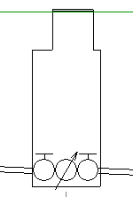
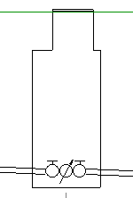
By changing the Size of fitting symbols you can adjust the size of the symbols so that they are not too large, but still maintain legibility. This option affects the drawings: profile and schema. In the diagrams below: on the left the symbol size is 80% and on the right 50%.
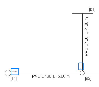
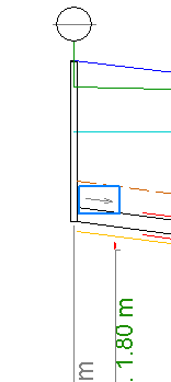
If you select the option Mark flow direction... on the longitudinal section and the schema drawing, arrows will be placed behind the first node in accordance with the flow direction selected in the Panel. The following examples show the flow direction markers (in blue borders) on the profile (left) and schema drawings.
Selecting the Place profiles' names on scheme drawing option causes the profile names to be applied to the schema drawing. This option can be particularly useful for multi-profile projects.
By clicking Default Infotable, you can choose a Infotable template that will be used by default in newly created projects.
For the changes have been saved even after you close the program, press the button Save.