ADDITIONAL DRAWING PARAMETERS
Settings > Drawing > Longitudinal section
Menu: Tools > Settings > Drawing > Longitudinal section
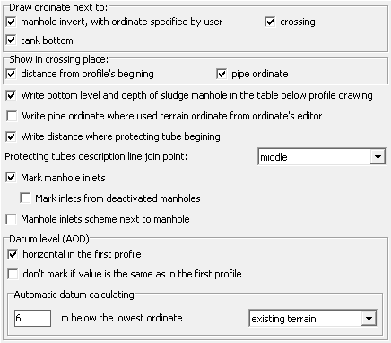
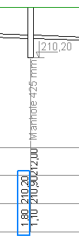
- Checking Draw ordinate next to... manhole invert, with ordinate specified by user option, will put on profile, next to the bottom of the manhole, the marker with ordinate value. This option applies only to those manholes for which the user has defined the ordinate.
Similarly, selecting this option on crossings or tanks causes the ordinate of the crossing or of the tank, on the created profile will next to the its bottom location.
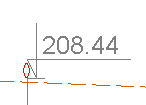
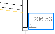
Below are placed samples with markers next to manhole and crossing.
- Checking Show in crossing place: distance from profile's begining and/or pipe ordinate options causes displaying distance and/or ordinate of the proposed pipeline to the table under the profile, in crossing's location.
- By checking Write bottom level and depth of sludge manhole... checkbox, in the table below profile additionaly, next to pipe ordinate and depth, appears bottom level and depth of the sludge manhole (if they are different of pipe ordinate and depth).
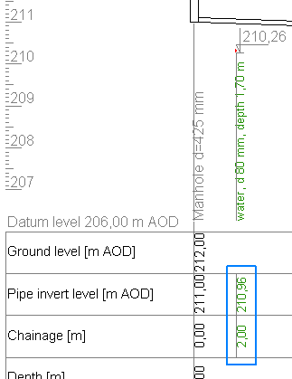
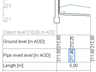
- Selecting the option Write pipe ordinate where used terrain ordinate from ordinate's editor causes the pipe ordinate (in the following figure in the blue border), to be entered in the table under the profile, in the place where the user has inserted an additional terrain ordinate.
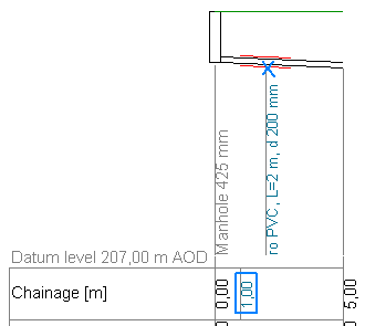
- Selecting Write distance where protecting tube begining option place of the beginning of the protecting pipe will enter the distance in the table below the profile.
- Option Protecting tube description line join point allows you to specify the location from which will be derived vertical profile description in the drawing. The choices are: a beginning, middle and end of the casing pipe. In the example below, "center" selected and marked with a blue cross.
- Selecting Mark manhole inlets... puts on manhole inlets ordinates (from other profiles/tabs located in the same project). Inlets are marked only for projects containing more than one profile.
- The Mark inlets from deactivated manholes option works only when the Mark manhole inlets... option described above is checked. Selecting it marks inlets on the manholes that also come from profiles that have been disabled from the Data tab.
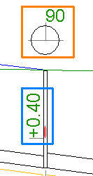
- Checking Manhole inlets scheme next to manhole checkbox causes placement of inlets scheme above manhole. This option also affects the placement of the connection diagram on the drawing of the cross section through the manhole. In the example below, marked with an orange border.
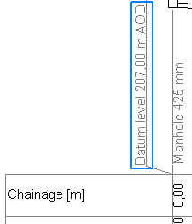
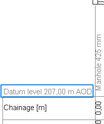
- To force the inclusion on the first profile string "Datum ground level..." horizontally check Horizontal datum in first profile.
The example on the left with the option selected:
- Checking the option Don't mark if value is the same as in the first profile allows to hide value of the datum level on profiles if this value is the same as in the first profile. This option is relevant only in projects with more than one profile.
- Using the options found in the group Datum level (AOD) > Automatic datum calculating, you can determine how the comparative terrain level is determined. It can be determined as the smallest value of one of the ordinates: the existing terrain level, the designed terrain level or the bottom of the pipe, decreased by the value specified by the user.