ENTERING DATA TO THE TABLE
Insertig data to the Data-table
In the Data-table one should enter details about nodes and sections of the considered profile. In the following table a characterization of individual data was compared:
| Column title | Sample | Unit | Description |
| Ground level | 212,50 | m AOD | in order to implement ordinates of the ground level different for left and right side of the node type e.g. : "212,11/210,50". Options the one it is possible to use at drawing e.g. the dodge, of terrace. |
| Invert level | 211,30 | m AOD | Using record like mentioned above for ordinate pipe bottom it is possible to get the cascade well (when the ordinate of the intake into the well is larger than of take-off) or pump station - implementing the ordinate from left smaller than from right. |
| Depth | 1,25 | m | |
| Length | 5,50 | m | |
| Gradient | 2 | % | enter the fall pipe preceded by a minus sign "-" (e.g. -2) we get the opposite drop pipe, eg pumping cord. |
| Material | PCV | - | choice between: PCV, PE, PP (how to add other material) |
| Diameter | 110 | mm | record e.g.: "110/160" will be interpreted by the program as "pipe in the pipe" (applying e.g.: thermal insulation of the pipe, sleeve protective tube) . |
| Chainage | 5,50 | m | value determined automatically. (Except for the first node where you can insert any value) |
| Object | - | - | Available objects and how to enter them in chapter Objects |
| Comment | any text value | - | placed below the profile at a given node typed text |
| Node | any text value | - | placed above the table name of the node |
| Line | 210,50 | m AOD | allows you to put on an additional line in profile, e.g. ground water level, the proposed land line, etc. Recording format analogous in "Ground level" column. (how to specify line name) |
| Angle | 45 | ° | inserts the value of the angle of refraction, together with the symbol of the direction. The introduction of a negative value will change the direction of collapse. |
| Trench width | 0,50 | m | value used to determine the volume of excavation and the creation of cross-sectional drawing. The use of recording such as: "1.20 / 0.80" allows you to get a sloping trench walls (the first value defines the "top" width of the trench and the second width measured at the bottom). |
| Section flow | 1,50 | m3/h | The flow that originates at a given section and at the beginning node of the section (with flow direction from left to right) or at the end node of the section with flow direction from right to left. The default flow unit [m3/h] can be changed in the Configuration window on the Data table tab. |
| Flow | 10,50 | m3/h | Total flow on a given section, with automatic consideration of preceding sections and inflows from connections. The value is calculated automatically and cannot be changed by the user. |
| X scale | 1000 | - | Horizontal scale (X) for a segment. This option is useful e.g. when the profile contains a long segment with no collisions. For such a segment a smaller scale can be set than for the whole profile. This will make the printout of the profile drawing shorter. |
| X coordinate | 1 | - | The X coordinate of the node. Length and angle values can be automatically calculated from the coordinates. The coordinates can be imported from a map in dxf format (menu: Profile > Import coordinates). If you need to scale coordinates after import, you can do it in bulk by clicking on the column heading in the table and selecting "Change value". |
| Y coordinate | 1 | - | The X coordinate of the node. |
| Bending radius | 1 | - | Pipe bending radius with value different from zero allows to have pipe in curved form on the profile drawing (instead of default straight section). This form can be useful e.g. when designing steerable jackings. Below is an example.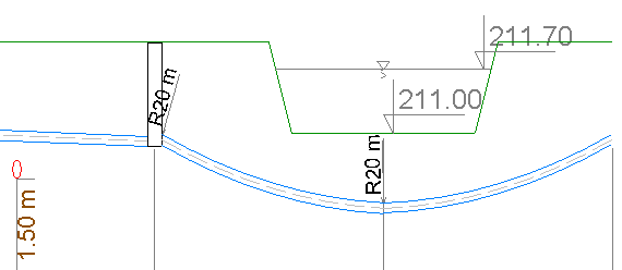 |
Current version:4.20
- Data table
- Data table - shortcuts
- Entering data
- Data exchange
- Network creating rules
- Searching data
- Profile parameters
- Crossings editor
- Protecting tubes editor
- Cross section editor
- Geological cross section
- Terrain description
- Boundaries description
- Additional ordinates
- Sewage treament plant
- Manholes
- Statistic
- Statistic - algorithms
- Materials' list