INSERTING CROSSINGS
Crossings editor
Methods of activation:
| icon: | menu: Tools > Protecting Pipe Editor |
 | keyboard shortcut: Ctrl+K |
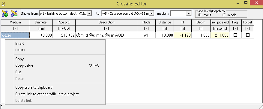
Crossings editor used to enter the crossings occurring in the profile. Crossings should be introduced after entering data in the Data table in the main window. The precision of the numbers placed in the window can be set in Configuration > Data Table > Decimal places. The user can filter the amount of crossings presented by selecting the nodes between which they are situated.
Editor columns description:- Network Type - name of the cable/pipe causing a collision (eg water, gas, phone, etc.).
- Diameter - diameter of pipe causing a collision given in millimeters. If the pipe has e.g. sleeve protecting tube or insulation diameter column needs to be filled as follows: "crossing_diameter/protecting_tube_diameter", where: crossing_diameter - diameter of the collision, protecting_tube_diameter - diameter casing pipe of a collision. Protecting pipe is also taken when generating the drawing.
- Pipe bottom ord. - bottom ordinate of pipe causing a collision given in m AOD
- Desripiton - Description of the collision, which will be shown in the drawing. The description can be used variables. Thanks to them, most of all collisions may have the same desription. User has access to the following variables:
- @m - network type
- @d - crossing diameter
- @o - sleeve protecting tube diameter
- @r - crossing pipe bottom ordinate
- @h - crossing distance from the designed pipeline
- @z - crossing pipe bottom depth
- @t - ground level at the point of collision
- @p - ordinate the designed pipeline at the point of collision (axis, bottom or top depending on the state Invert level on the Data tab)
- @pd - ordinate the bottom designed pipeline at the point of collision
- @po - ordinate the axis designed pipeline at the point of collision
A sample entry in the first collision in the screenshot above "@m fi @d mm @r" while creating a drawing will be replaced by text "water fi 40 mm 211.80" and as such placed on it.
- Node - node name (from Data table), which will be given the distance to collision. When you edit this value you must select a node from a list of existing ones. Crossing is assigned to the selected node, ie, the user can freely change its position in the table each time without the need to update the position of the collision.
- Distance - distance from node from Node column to axis crossing pipe. This value can be negative if it refers to an existing node for the collision.
- H - projected pipeline outline distance from the outline pipe/cable causing a collision, specified in meters.
This value can not be modified by the user. It is continuously updated by the program. Values preceded by "+" means that a collision is over, the designed line, while the sign "-" - under it. Marked in red are designed collisions passing through the pipeline, then column value is "0". If, however, one tube line (projected or conflicting) "shall" in the pipe casing of the second (or an aspect only shielded pipes), the text cells turn red, and the value in it is different from zero. - Depth - collision depth expressed in meters above sea-level. If user knows collision depth and does not know the ordinate may in this column, enter the value. Then the column Pipe bottom ord. will be updated automatically. Entering data in this column is only necessary when there has been supplemented by a column Pipe bottom ord..
Columns: Network Type and Description have the ability to be quickly populated with user-defined names in the Configuration window under Most-used values.
If "error" appears in the H or Depth column, it may mean that a collision was entered outside the profile (before the first or after the last node). Collisions added automatically are described as italic formatted text.
If the collision is a pipeline located in the same project (file), then the collision can be "linked" with it by right-clicking on it and selecting Create link with other project profile (the option is available after selecting a node and a distance from it to the collision). After selecting the option, in the window that opens, choose the profile, node and the distance from it where the collision occurs. The associated collision has automatically updated values for the network type, ordinate, depth and diameter. This means that if the depth of the colliding pipe changes, it will automatically be included in the collision parameters, without the need for manual adjustments. To remove the connection, right click on the mouse and select Remove connection.
Keyboard shortcuts:
F2 - goes to edit cell;Insert - inserts a new node (row) above the currently selected one;
Delete - deletes the currently selected node;
Cursor down ↓ - if the last node is currently selected, adds a new one at the end of the table;
Shift + cursor down ↓ - copies the contents of the selected cell to the cell below;
Shift + cursor up ↑ - copies the contents of the selected cell to the cell above;
Shift + Alt + cursor down ↓ - copies the data of the current collision to the collision below;
Shift + Alt + cursor up ↑ - copies the data of the current collision to the collision above;
Ctrl + cursor down ↓ - moves the current collision one position down;
Ctrl + cursor up ↑ - moves current collision one position up;
Ctrl + C - copies the selected cell to the system clipboard;
Enter - validates the entered data and closes the cell editing mode;
[click on column title] - selects entire column;
Current version:4.20
- Data table
- Data table - shortcuts
- Entering data
- Data exchange
- Network creating rules
- Searching data
- Profile parameters
- Crossings editor
- Protecting tubes editor
- Cross section editor
- Geological cross section
- Terrain description
- Boundaries description
- Additional ordinates
- Sewage treament plant
- Manholes
- Statistic
- Statistic - algorithms
- Materials' list