PROFILE PARAMETERS
Basic profile parameters
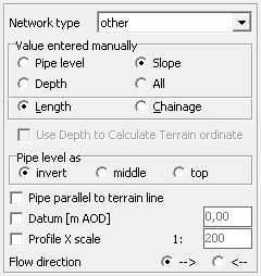
The basic parameters of each profile contained in the project/file can be changed on the Panel on the Data tab (see the Data table chapter for ways to activate the Panel).
In the Type drop-down list, you can select the type of pipeline to be designed from:
- water supply,
- sewage system,
- storm water,
- gas pipeline,
- heat pipeline,
- melioration,
- other.
The selected pipeline type affects, among other things: the way flows are summed up, creation of scheme drawing (pipelines of the same type are connecting automatically), automatic updating of pipe ordinates in the same named nodes.
By default, the automatically determined values in the Data table are: pipe ordinate, pipe depth. The value that needs to be entered manually is pipe slope.
These settings can be changed by marking as Specify column with manually inserted values:
- Pipe level (ordinate) - the program automatically determines the value for pipe depth and slope,
- Pipe depth - the bottom ordinate and slope are calculated automatically,
- Slope - the program automatically determines the ordinate and the bottom depth,
- All- only the distance or length is determined automatically, depending on the settings.
The manually entered value can also be changed by double-clicking in the Data table on the column heading whose values are to be manually changed.
When Use depth to calculate terrain ordinate checkbox is checked (can only be selected when Depth is selected as the manual input value) determines the ground ordinate based on the Depth and Pipe ordinate values (Pipe ordinate must be specified in the first node).
The Pipe level column in the Data table can indicate one of the following values:
- The bottom of the pipe (invert),
- The centerline of the pipe (middle),
- Top of the pipe (top).
The choice should be made in the Pipe level options group. The choice also affects the way of joining pipes on the profile, e.g. if there is a reduction in diameter at a node, selecting the option Pipe top will align the tops of pipes.
When the Pipe parallel to terrain line checkbox is checked, after entering the Depth value in the first node and entering, subsequent Terrain ordinates, the program automatically determines the characteristic values of subsequent sections so that the pipe line runs parallel to the terrain line.
By default, the comparison level is determined automatically by the program. Sometimes, there is a need to specify a different value, then you should select Datum checkbox and enter an appropriate value into edit field. If project contains more than one profile, after confirming entered value you can assign it to other profiles by choosing appropriate button in displayed dialog window.
By default the X (horizontal) scale of the profile drawing is assumed as entered in the table (or calculated by the program) in the Preferences window. If there is a need to specify a different value of X scale for the selected profile, then select the X scale option and enter an appropriate value into the edit field. If project contains more than one profile, after confirming entered value it is possible to assign it to other profiles, selecting appropriate button in displayed dialog window.
By clicking on the appropriate mark, you can specify the Flow direction, from:
- --> left to right, that is, from the first node/row in the Data table to the last,
- <-- right to left, which is the opposite of the above.
The flow direction can be plotted on drawings. To do so, select the checkbox Mark flow direction on longitudinal section and scheme drawings... in the Preferences window on the Drawing tab.
Current version:4.20
- Data table
- Data table - shortcuts
- Entering data
- Data exchange
- Network creating rules
- Searching data
- Profile parameters
- Crossings editor
- Protecting tubes editor
- Cross section editor
- Geological cross section
- Terrain description
- Boundaries description
- Additional ordinates
- Sewage treament plant
- Manholes
- Statistic
- Statistic - algorithms
- Materials' list