ADDITIONAL DRAWING PARAMETERS 2
Settings > Drawing > Longitudinal section 2
Menu: Tools > Settings > Drawing > Longitudinal section 2
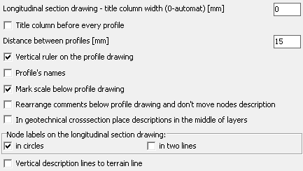
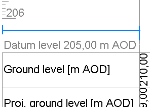
The edit field Title column width... is used to specify the width of the title column in the table under the profile. If a value of 0 (zero) is entered, the width is automatically determined as narrow as possible based on the length of the titles. The width must be expressed in print millimetres. In the example, the column width is indicated by a blue dimension line.
- If the option Title column before every profile is selected, a column with the titles of the rows is placed under the profile drawing before each profile. If the option is unchecked, the title column is placed only before the first profile. This option is only applicable to projects with more than 1 profile.
- Edit box Distance between profiles [mm] is used to determine the interval between each picture profiles (if the project contains more than one profile). The distance should be expressed in millimeters of print.
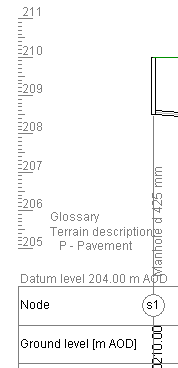
- Checking Vertical ruler on the profile drawing checkbox place ruler on the left side of the drawing. It's makes easy measure objects ordinate which it hasn't directly specified. If project includes more than one profile ruler is placed only when profile datum level is different from previous.
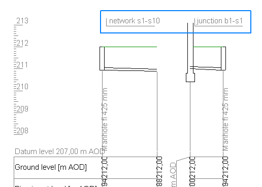
- When the Profiles names option is selected, the profile names (those displayed on the tabs under the Data table) will be inserted at the top of each profile drawing. In the example below, the inserted profile names are surrounded by a blue border.
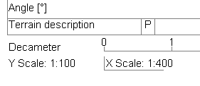
- By checking Mark scale on the profile drawing is possible to place information about scales values below table on the profile drawing. Information is also placed, regardless checkbox state, if project contains profiles with different horizontal scales values.
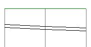
- The option Rearange comments... allows one of two algorithms to be selected, responsible for the way in which overlapping: comments, collision descriptions, etc., are spread over the profile drawing. When enabled, it allows node descriptions to be left in place, if possible.
Sample with unchecked (on the left) and checked:
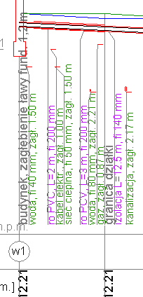
- An option In geotechnical... determines form and place of descriptions on cross-section.
- Group of settings Node labels... has an influence on placing node labels on the longitudinal section drawing.
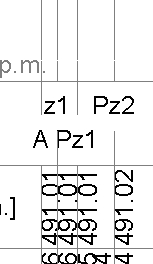
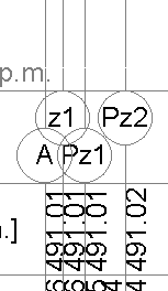
When in circles checkbox is unchecking nodes are placed on drawing without surrounding circles. Unchecking may helps when node labels contains more than 3 characters and they goes out beyond circle.
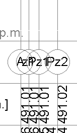
In case small distances between neighbour nodes may be useful to check in two lines checkbox. It allow to placing nodes in two lines. It decrease probability of overlapping labels.
Sample with unchecked (on the left) and checked option:
-
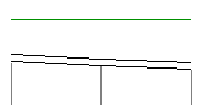
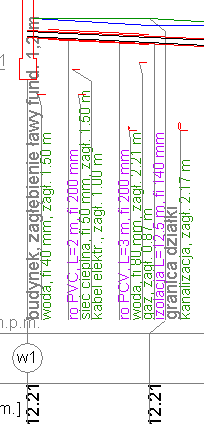
If the option Vertical description lines to terrain line is selected, the vertical line of description/commentary above the pipe is extended to the site line. With the option off, the vertical lines are only under the pipe.
Sample with unchecked (on the left) and checked option: